Julian Straub
creations and thoughts
Voltage Sources
Creating a stable voltage of known quantity from a some a given input voltage (from a battery, or a solar cell for example) is a common problem. There are various completely integrated ICs that need few external components. In order to better understand them and other, simpler, ways of generating a fixed voltage, I built the following succession of different voltage sources (unregulated and regulated).
Zener-based Voltage Source

Similar to using the forward voltage (0.6V) of a standard diode, we can use the reverse breakdown voltage of a Zener-diode to obtain a fixed voltage. Note the backward orientation of the Zener diode. Zener-diodes can be bought with various Zener voltages. They have usually have a 5% tolerance but it is possible to find 1% versions. There are a lot of problems with this design. One of the main ones being that the load is supplied current through the same resistor as the Zener.
Transistor-based Voltage Source
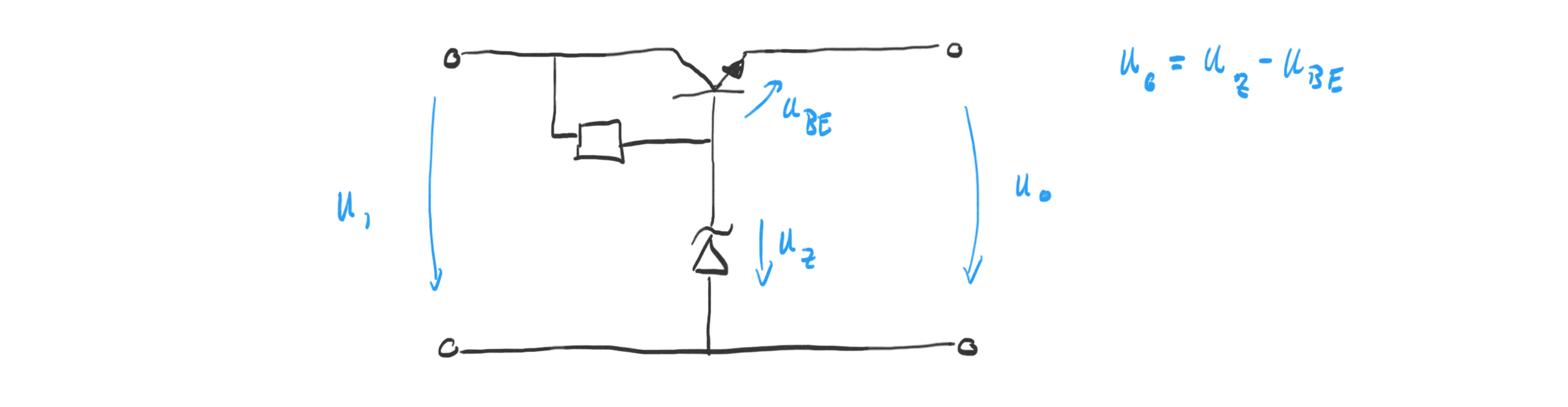
The transistor is held on by the resistor between collector and base. This
resistor also supplies current to the Zener-diode. Given a high enough current
through the resistor, the output voltage is
\(U_{BE} + U_Z\)
.
The problem with this circuit is the choice of the resistor if the input voltage
has a large range and the fact that the output voltage cannot be adjusted
easily and is constrained by the available Zener-diodes.
Transistor-regulated Voltage Source
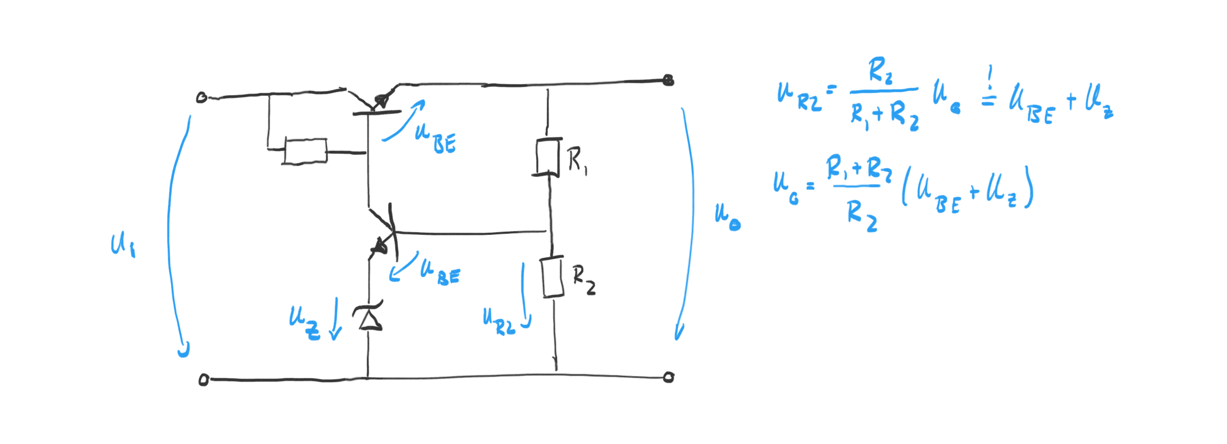
Similar to the previous circuit, the main transistor (in series with the input), is held on by the resistor next to it. The important difference is the second transistor which starts “robbing” base current from the main transistor if the voltage over
\(R_2\)
deviates from
\(U_{BE} + U_Z\)
. Note that it is perfectly fine to remove the Zener-diode from the circuit.
The second transistor adds a negative feedback loop to the circuit and
stabilizes the output within the amplification range of the transistors. In this
design the output voltage is adjustable using the voltage divider.
OpAmp-regulated Voltage Source
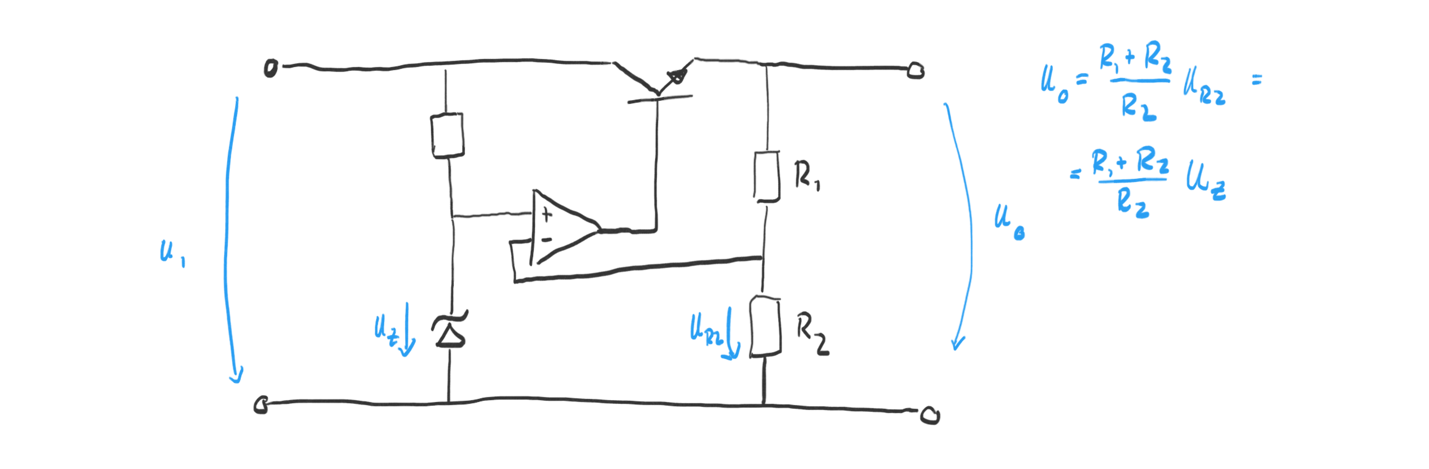
The OpAmp in this circuit does the same job as the second transistor in the previous circuit. It regulates the output voltage based on the ratio of the voltage divider on the output. The transistor at the output of the OpAmp makes it possible to control high currents.