Julian Straub
creations and thoughts
Sensing Light
Sensing the amount of light falling on a surface is at the core of how any more advanced light sensors such as human or animal eyes function. This makes it an interesting problem to investigate from an electrical perspective. In the following, I show two ways of converting incident light on a photo-diode into an output voltage that could be used for downstream processing.
Linear Light Sensor
The simplest light sensor just amplifies the photo-current produced by the photo-diode using an OpAmp as shown in the circuit below.
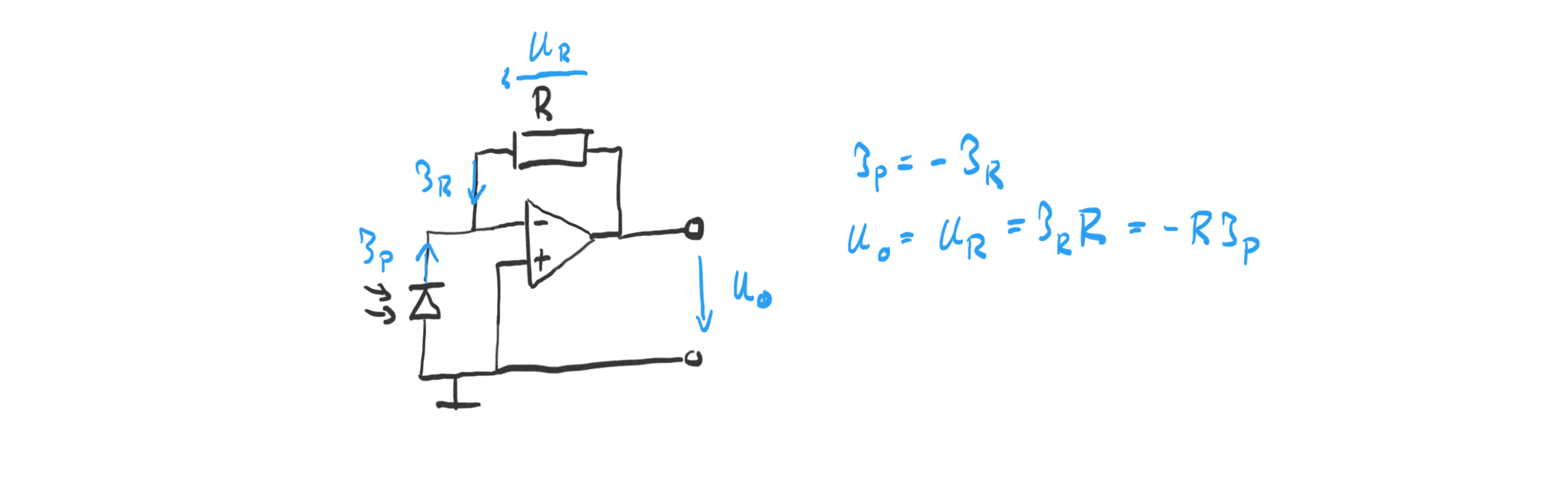
The OpAmp adjusts the output voltage
\(U_o\)
such that the current through the resistor R equals the photo-current
\(I_p\)
. By choosing a large resistor, the small photo-current can be amplified to measurable voltage levels.
I used a BPW34 photodiode and a resistor of
\(R=100k\Omega\)
, and the LM358N OpAmp with an operating voltage of
\(\pm 5V\)
.
Diode-based Logarithmic Light Sensor
It is well known that the human perception of light is logarithmic in the amount of incident light. This made me curious to build a logarithmic amplifier for the photo-current to measure light in the “perceptual units”. Commonly log-amplifiers are built using matched transistors to compensate for temperature changes. Since these are expensive or only available in SMD packages, I decided to just try and see how well a simple diode-based log-amplifier would do.
In both cases, the trick is to use the logarithmic relationship between the current through np-junction (here a diode):
$$U_D = -U_T ln(I_D/I_s+1) \approx -U_T ln(I_D/I_s)$$
The full diode-based logarithmic light sensor circuit is shown below:
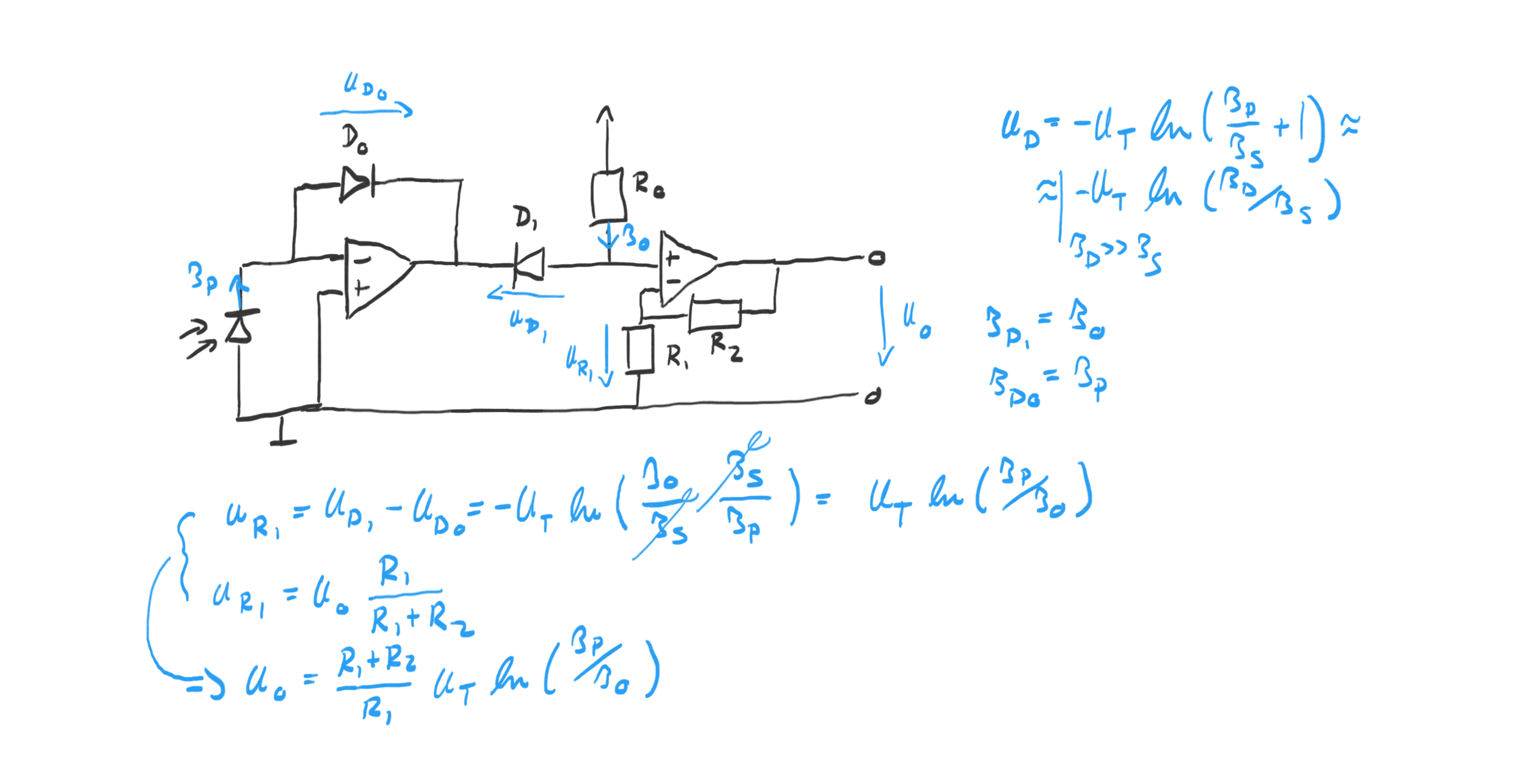
The input OpAmp forces the photo-current
\(I_P\)
of the photo-diode through diode
\(D_0\)
. The second diode
\(D_1\)
gets a current
\(I_0\)
supplied via
\(R_0\)
. The output voltage
\(U_O\)
is a scaled version of the voltage over
\(R_1\)
,
\(U_{R1}\)
. The key relationship derived in the figure above is:
$$U_{R1} = U_T ln(I_P/I_0)$$
The use of two diodes cancels
\(I_s\)
(this is assuming that they are matched) and makes the voltage
\(U_{R1}\)
a function of the logarithm of the photo-current. The current
\(I_0\)
sets the point at which the output is 0V (i.e. when
\(I_P=I_0\)
) and can be adjusted by adjusting
\(R_0\)
.
In the experiment, I used standard 1N4148 diodes, a LM358N OpAmp, a BPW34 photo-diode,
\(R_0=2M\Omega\)
,
\(R_1=1k\Omega\)
, and
\(R_2=10k\Omega\)
.
Comparison
In my room, I did a simple experiment of varying the incident light to test the behavior of the two circuits:
| Light Condition | Linear Output | Log Output |
|---|---|---|
| iPhone LED | -4V | -1.56V |
| Light On | -0.175V | 0.13V |
| Shadow | -0.031V | 0.96V |
| Light Off | -0.003V | 2.10V |
Perceptually these four lighting conditions are noticeably different. The linear output changes by roughly an order of magnitude between the lighting conditions. The logarithmic output changes linearly similar to how I perceived the changes in lighting as well. This demonstrates that the human perception system is logarithmic and shows why it might sometimes make sense to use a log amplifier to measure light in a “perceptual scale”.