Julian Straub
creations and thoughts
Setup and Programming the new ATtiny Microcontrollers
The new ATtiny-0 and ATtiny-1 microcontrollers have really nice peripherals and are promising replacements for the old ATtiny85. While others do seem to miss the ISP interface, I think the new UPDI interface is actually really neat since it allows for way smaller programming connector of only three pins instead of the six pins used for ISP.
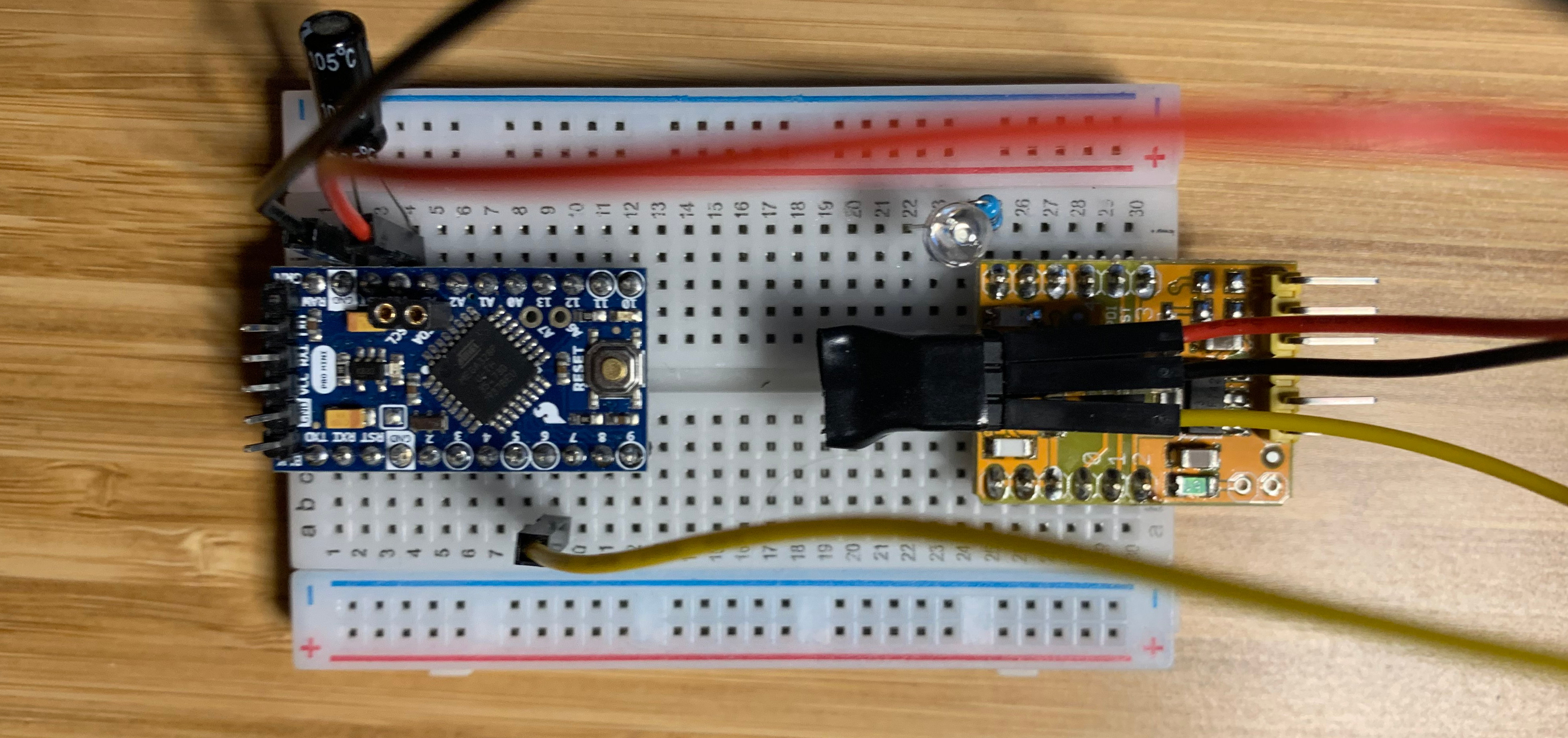
Others have written at length about how to build a UPDI programmer and get started with Arduino on the new microcontrollers. To test it out I got a ATtiny412 breakout board from Spence Konde. Here are the steps I needed to go through to program it:

- Make a UDPI programmer is pretty straight forward. If you use one of the aforementioned ATtiny boards of Spence Konde the UPDI resistor is integrated.
- Get jtag2updi from here and flash it onto your arduino that will be used as a programmer. I have verified that jtag2updi works for Arduino Nanos as well as apparently with Arduino Mini Pros as long as they do not have a bootloader. Mini Pros with a bootloader are not supported.
- Connect the ATtiny to the UPDI pin (P6 on the Arduinos). Don’t forget the resistor if its not on the ATtiny board.
Install the megaTinyCore board extension in the Arduino IDE by adding
https://github.com/SpenceKonde/megaTinyCore/blob/master/Installation.md
to the board manager URLs and then finding and installing the megaTinyCore board extension.
Select the right settings (desired clock speed etc) in the Arduino IDE drop down and flash bootloader. Without first flashing the bootloader with the settings below, my ATtiny412 board did not work as expected. For the ATtiny412 3.3V version from Spence, I changed the following from the defaults:
10Mhz internal clock
2.6V BOD
Upload a program like a simple blink program to test everything. For the ATtiny412 board from Spence, I had to define the default LED pin as:
#define LED_BUILTIN 1