Julian Straub
creations and thoughts
Two Transistor LED Current Source
For various reasons we may want to control the current through a load. For example current control is a great way to drive LEDs. In a previous post on creating light, I showed a single transistor and diode circuit current source. The main drawback of that circuit is that it requires two diodes and hence has a minimum voltage requirement of 1.2V to set the reference voltage.
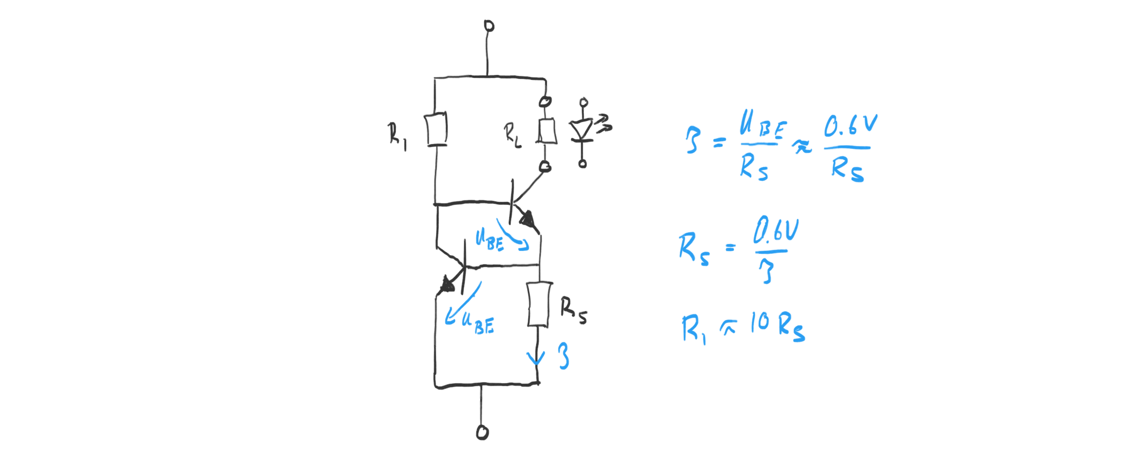
The npn-transistor-based circuit below removes that requirement and drawback by replacing the two diodes with a second transistor.

The current forced through the load $R_L$ is determined by the sense-resistor $R_S$ as:
$$ I = \frac{U_{BE}}{R_S} = \frac{0.6V}{R_S} $$
Hence we the sense-resistor should be picked as:
$$ R_S = \frac{0.6V}{I} $$
The other resistor $R_1$ delivers the base current to the upper transistor. It should be sufficiently small to saturate that transistor for the desired current. Assuming a save beta of 10 for the transistor, we would choose
$$ R_1 = \beta R_S = 10 R_S $$
If we replace the load resistor with a LED, we can drive a desired current through the LED that is determined by $R_S$. The current source circuit thus arranged around the LED increases the LED forward voltage by 0.6V needed for regulating the current.
If we desire a regulated current for a LED, we can “wrap” it by this current source circuit and only “pay” via an increase of the forward voltage of 0.6V.